How to Make Almost* Anything | MAS.863
Ella Peinovich | M.Arch Level III, MIT
Ella Peinovich | M.Arch Level III, MIT

Light Sensor Array
In order to test the potential and sensitivity of the light sensors we have in the lab, this week I embedded 3 phototransistors within a simple curved paper screen to resemble the effects of light gradients on an undulating structural wall design. By having an array of sensors I anticipate that I will be able to use sensing patterns to differentiate between different types of shadow and light generators, and also detect the angle of the light source.
Effect 01 |By comparing individual light sensors to the average of light across the wall I could sense gradual light shifts like day to night light levels from more temporal, local environmental conditions like a person passing by the wall and casting a shadow.
Effect 02 |By then comparing the detection vs absense of light across a series of sensors on a single curve, I would also be able to determine the angle of the light source which would lead me to many new discoveries
This week was an ambitious week. On top of being assigned the task of 01|designing and then 02|fabricating my own circuit with a sensor (or three), I had to also 03|program the microncontroller and then 04|write a program (in my case using python) to read and display the value from the sensors streaming through the microcontroller.
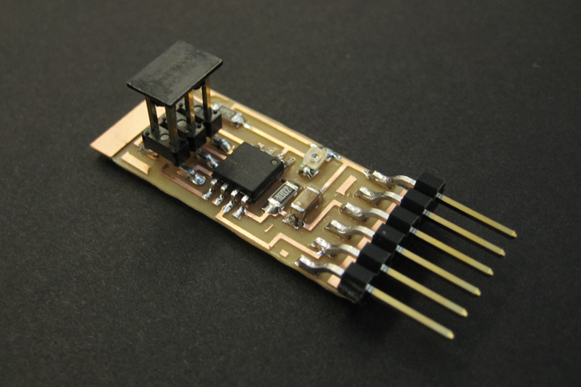
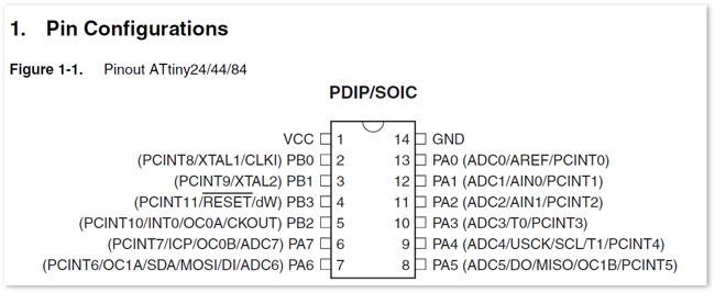 I designed my board in Eagle while closely attached to the attiny44 data sheet
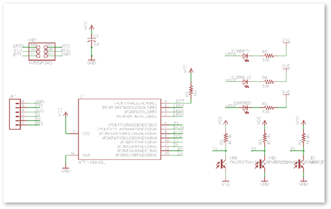
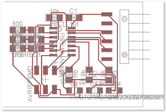
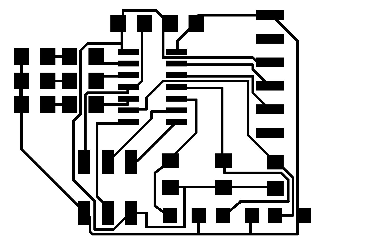
Step 01| Designing the Schematic and Artwork of the Circuit board
I added the 3 sensors on PA pins, while all of the LEDs were placed on the PB pins. I hope to be able to articulate the reason for this more later. The .png file for my board is available here for download: Fab3Sensor
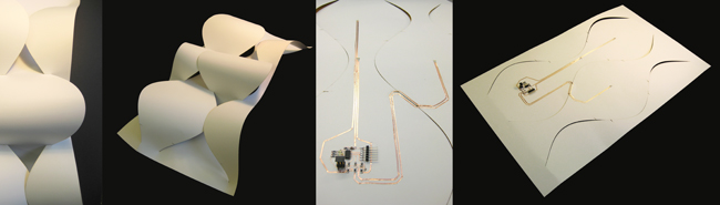
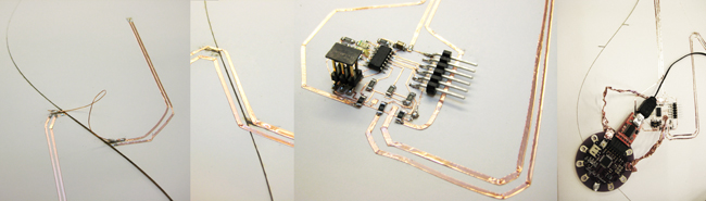
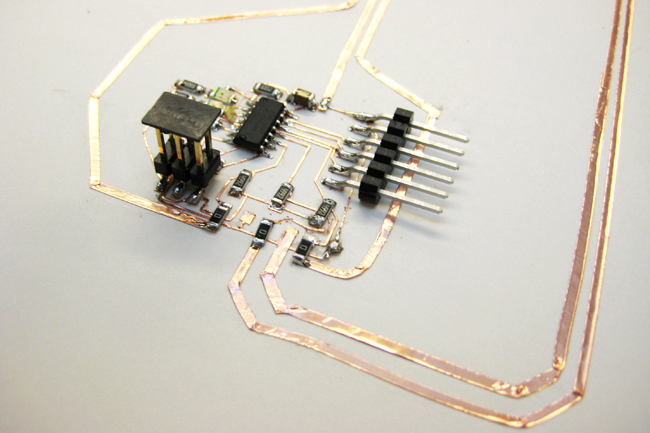
Step 02| Laser cutting, Vinyl cutting and Customizing the traces of the circuit board
Seen above, I attempted at several methods of running the copper traces a distance and for bridging the gaps that will be later connected when the wall is folded into shape.
Taking some liberties with the designed and cut circuit I added three 0 Ohm resistors to bridge over the ground trace in order to run the circuit outward. It worked very well to just cut some thin strips of copper tape from a sheet and peel and place as needed.
Step 03| Programming the MicroController
Coding the Program: Admittedly, I required a lot of patient teachers this week. But was able to get through it to create some kind of legible code. I began with Neil's light sensor code, however rewrote it to communicate with an attiny44 rather than the 45 and added 2 sensors and 3 LEDs.
Loading the Program: I first dowloaded the USBtiny Driver for Cygwin, making sure to add the driver for Windows 7. (This may however still be where my glitch is in the whole system, because I continue to get the error: Could not find USBtiny device.) Jie was kind enough to let me use her computer to run my make file and program file.
Using the Make file on a PC required that I used Windows command line and that I used the command 'export TEMP=/ tmp', before using the 'make' command. I then editted the make file to read my attiny44 by editing the function to read as follows:
program-fabisp: $(PROJECT).hex
_____avrdude -p t44 -c usbtiny -U flash:w:$(PROJECT).c.hex
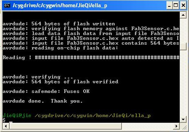
It worked!
 Step 04| Programming in Python
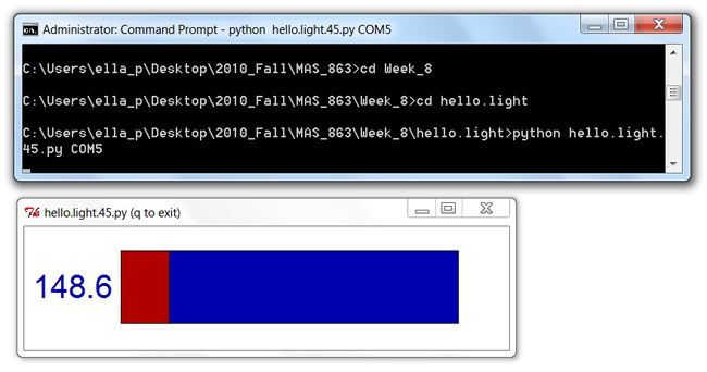
After gaining confidence replicating the predesigned board and code that Neil provided called "hello.light.45.py. I began to write the code for my Fab3sensor display by hacking together Neil's python code for the light sensor. I first added a way of reading each of the 3 sensors seemingly simultaneously by introducing 2 new filters in the code and working out a new canvas for the graphs.
Here is a link to a site that provides the color codes which can be adjusted:: Hexadecimal Color Codes
Unfortunately, I do not have a fully functioning program yet, but I do have a graphic!
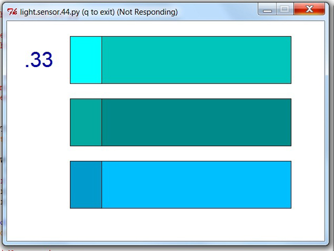
Any suggestions and lessons about coding are welcome: Fab3Sensor.py_not functioning
Programming Goals: At a minimum for my finalI would like to have an embedded circuit within my wall module that can sense the light levels on the wall and then turn on a light source that will in the most banal setting offset the change in light from outside, or mimick the weather and environmental patterns outside. Time permitting I would like to add a mechanical function to the wall, allowing it to open and close with the added function of the embedded light source to further diffuse or reflect light.